Connecting the 6-pin Harness
Before plugging into the EP1 Alarm Unit, connect the wiring harness as follows:
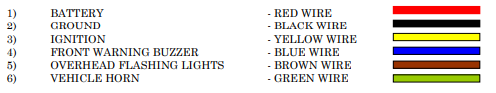
- BATTERY - RED WIRE
- GROUND - BLACK WIRE
- IGNITION - YELLOW WIRE
- FRONT WARNING BUZZER - BLUE WIRE
- OVERHEAD FLASHING LIGHTS - BROWN WIRE
- VEHICLE HORN - GREEN WIRE
- Connect the RED wire to a 12-volt battery- always in the positive mode.
- Connect the BLACK wire to a viable ground connection.
- Connect the YELLOW wire to ignition - 12 volts.
- Find the bus’ front warning buzzer. It has two wires-one runs to the rear door switch while the other becomes positive when the ignition is turned on. Join the BLUE wire of the Child CheckMate Safety Systems™ to the wire running to the rear door switch.
- The BROWN wire is the activation wire, which you connect to the overhead lights. Ensure that it does become live whenever the overhead lights are activated. Never connect this wire to the master switch!
- Find the bus’ horn relay and connect the GREEN wire to its grounded side.
Note: You may need to run extra 18-gauge wire if the relay or ground wire is located under the steering column. If there is no horn relay, one must be installed.